
How to Choose an Air Conditioner Contactor in 2026?
Choosing the right Air Conditioner Contactor in 2026 requires more than matching voltage and horsepower. This small switching device controls compressor and fan motors, often under demanding starting conditions. A poor choice can cause buzzing, welded contacts, nuisance trips, or premature compressor damage. The correct selection begins with the equipment nameplate, wiring diagram, and manufacturer specifications. Check the motor’s rated load current, locked-rotor current, coil voltage, contact configuration, and operating frequency. Never rely on appearance alone.
Field experience shows that installation details matter as much as catalog ratings. A contactor exposed to heat, dust, moisture, or frequent cycling needs suitable durability and enclosure protection. Verify the pole arrangement, terminal capacity, mounting pattern, and compatibility with the existing control circuit. For modern systems, consider diagnostics and dependable coil performance, but avoid paying for features the unit cannot use. Standards and certification markings also deserve careful review. They provide useful evidence, not an automatic guarantee.
Small details matter.
A familiar brand can still be the wrong fit. A lower-priced model may look attractive, yet weak contacts can create costly downtime. Conversely, an oversized contactor may not solve a control-voltage mismatch. This guide examines practical selection criteria, common mistakes, and verification steps for residential and light commercial equipment. It also recognizes an uncomfortable truth: documentation is sometimes incomplete, and field conditions may differ from the design assumptions. When uncertainty remains, confirm the specifications with a qualified HVAC professional and follow the equipment manufacturer’s instructions. Reliable selection is not guesswork; it is a careful comparison of electrical data, operating conditions, and long-term service needs.
Understand the Role and Types of Air Conditioner Contactors
How to Choose an Air Conditioner Contactor in 2026?
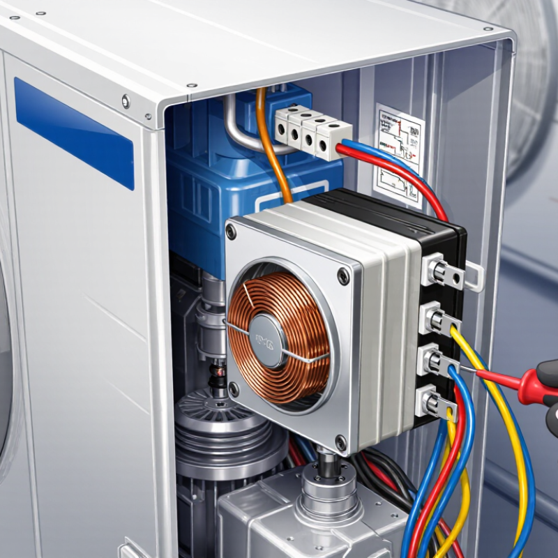
An air conditioner contactor is an electrically controlled switch. It connects the compressor, condenser fan, or electric heater to the power supply. The control board sends a low-voltage signal, while the contactor handles higher current. It must interrupt motor loads safely. A loose, undersized contactor may cause buzzing, overheating, or burned terminals.
Types matter. Electromagnetic contactors remain common in split systems and packaged units. Solid-state contactors switch quietly and reduce mechanical wear, but they need suitable heat dissipation. Select the correct pole count for the circuit. Check coil voltage, full-load current, locked-rotor current, horsepower rating, utilization category, and short-circuit rating. AC-1 ratings suit mostly resistive loads; compressor motors usually require a motor-duty rating, such as AC-3. Never choose by physical size alone.
The U.S. Department of Energy reports that heating and cooling use about 48% of energy in a typical American home. The International Energy Agency’s 2018 cooling report projects global cooling demand could more than triple by 2050. That makes dependable switching increasingly important. In field work, I also inspect terminal torque, enclosure temperature, and auxiliary contacts. Small details matter. Yet one assumption deserves review: a higher current rating is not automatically better. Excess capacity can increase cost, while the wrong coil voltage can stop the system completely. Verify the nameplate and the installation conditions before replacing anything.
How to Choose an Air Conditioner Contactor in 2026?
Understand the role and types of air conditioner contactors by comparing typical pole configurations and rated-current ranges used in air-conditioning equipment.
How to read this chart: Two-pole contactors are commonly used for single-phase air-conditioning equipment, while three-pole contactors are typically used for three-phase equipment. The selected contactor should match the system voltage, compressor full-load current, locked-rotor current, pole arrangement, coil voltage, and local electrical requirements. The ranges shown are typical reference values and should be verified against the equipment nameplate and contactor datasheet.
Check Voltage, Current, Poles, and Load Compatibility
How to Choose an Air Conditioner Contactor in 2026?
Choosing an air conditioner contactor starts with voltage, not appearance. Check the coil voltage against the control circuit. Common choices include 24V AC, 120V, and 240V. A mismatch can cause humming, overheating, or complete failure. Then inspect the equipment nameplate. Record the rated voltage, full-load current, and locked-rotor current. The contactor must handle the compressor and fan motor load, not just the normal running current.
Poles matter too. A two-pole contactor switches two energized conductors, while a three-pole model suits many three-phase systems. Never assume more poles are automatically safer. Confirm the wiring diagram and disconnect requirements. Select ratings designed for motor loads, including horsepower and approved utilization categories. I once focused too much on physical fit and overlooked the coil rating. It looked correct. It was not. Also check terminal size, enclosure space, and the system’s short-circuit rating. These details affect reliability in a hot, vibrating outdoor cabinet.
Tips: Photograph the old wiring before removal, but do not copy it blindly. Verify every terminal with the manufacturer’s diagram. Compare the contactor’s voltage, current, poles, and motor rating with the unit nameplate. If readings seem inconsistent, stop and investigate. A licensed technician should handle live-circuit testing and replacement. Small errors can damage a compressor or create a serious electrical hazard.
Match the Contactor to the Air Conditioner System
Choosing an air conditioner contactor in 2026 starts with the system, not the catalog photo. Identify whether the unit uses a single-phase or three-phase compressor. Count the switching poles required by the equipment design and local electrical rules. A split air conditioner may use a two-pole contactor, while a three-phase condenser normally needs three poles. Do not assume every outdoor unit follows that pattern. Some inverter-driven systems use electronic power modules instead of conventional contactors.
Read the compressor data plate before comparing contactor ratings. Check running current, locked-rotor current, voltage, horsepower, and the applicable utilization category. The contactor should support the compressor and fan loads under their actual operating conditions. Relying only on running amps can create a weak selection. The label can mislead. A contactor also needs the correct coil voltage, such as 24 VAC, 120 VAC, or 240 VAC. Check the coil voltage.
Consider the installation environment as part of the match. An outdoor condenser may face heat, moisture, dust, vibration, and frequent cycling. Confirm the contactor’s temperature range, enclosure suitability, terminal capacity, and short-circuit coordination. The contactor does not replace overload protection, fuses, or a properly sized disconnect. Experienced technicians still recheck wiring diagrams, because a small control-voltage error can leave the compressor silent or cause rapid contact wear. For unusual heat-pump configurations, verify the manufacturer’s electrical specifications instead of guessing from a similar model.
| Air Conditioner System | Typical Supply Voltage | Phase | Typical Contactor Poles | Common Coil Voltage | Load Information to Verify | Recommended Contactor Selection | Important Installation Notes |
|---|---|---|---|---|---|---|---|
| Residential split air conditioner | 208–240 V AC | Single-phase | 2 poles | 24 V AC is common; confirm the control voltage | Compressor and condenser-fan motor rated-load current, locked-rotor current, and motor horsepower | Two-pole definite-purpose contactor with voltage and motor ratings meeting or exceeding the nameplate requirements | Both ungrounded supply conductors are normally switched. The equipment grounding conductor must not be switched. |
| Residential heat pump | 208–240 V AC | Single-phase | 2 poles; additional contacts may be required for auxiliary functions | 24 V AC is common; verify the control-board specification | Compressor, outdoor fan, defrost operation, auxiliary heat, and nameplate current values | Two-pole compressor contactor sized for the heat-pump compressor and outdoor fan; use separate switching devices where the design requires them | Do not assume a standard cooling-only control sequence. Defrost and auxiliary-heat circuits may require separate relays or contactors. |
| Three-phase commercial condensing unit | 208–230 V AC or 460–480 V AC | Three-phase | 3 poles | 24 V AC, 120 V AC, or another control voltage depending on the unit | Compressor full-load current, locked-rotor current, motor horsepower, system voltage, and phase sequence | Three-pole contactor with a voltage rating suitable for the system and motor-duty ratings equal to or greater than the equipment requirements | Confirm the contactor is suitable for three-phase motor switching. Check rotation after installation if the compressor or fan is phase-sensitive. |
| Packaged rooftop air-conditioning unit | 208–230 V AC or 460–480 V AC | Single-phase or three-phase | 2 poles for single-phase; 3 poles for three-phase | 24 V AC is common; some controls use line-voltage coils | Compressor and supply/outdoor fan motor loads, minimum circuit ampacity, and maximum overcurrent protection | Select the pole count, coil voltage, and motor-duty rating to match the complete package-unit nameplate | Packaged units may contain several internal contactors. Replace only the device serving the identified load and match the original control sequence. |
| Commercial split system with multiple compressors | 208–230 V AC or 460–480 V AC | Single-phase or three-phase | One contactor per independently controlled compressor circuit | 24 V AC is common; verify each control circuit | Each compressor’s rated current, locked-rotor current, motor horsepower, and staging sequence | Use individually sized contactors for each compressor unless the equipment manufacturer specifies a common switching arrangement | Do not size one contactor from the total cabinet current unless the wiring diagram and listed equipment ratings permit that arrangement. |
| Electric resistance auxiliary heat or strip heat | 208 V AC or 240 V AC | Single-phase or three-phase | 2 or 3 poles, based on the heater circuit | 24 V AC, 120 V AC, or line-voltage coil depending on the heater controls | Heater kW rating, circuit amperage, number of stages, conductor size, and overcurrent protection | Use a resistive-load-rated contactor with adequate continuous-current capacity and the correct number of poles | Motor-duty ratings alone are not sufficient for electric heat. Confirm the contactor is rated for the intended resistive heating load. |
| Inverter-driven mini-split or variable-speed system | Typically 115 V AC or 208–240 V AC | Single-phase | Often no conventional external compressor contactor | System-specific low-voltage or electronic control | Manufacturer wiring diagram, inverter input current, disconnect requirements, and indoor/outdoor communication wiring | Do not add a standard contactor unless the system documentation specifically permits it | Frequent switching of inverter power can cause faults or damage. Follow the unit’s approved disconnect, control, and service procedures. |
| Fan-only or condenser-fan motor circuit | 115 V AC, 208–230 V AC, or 460–480 V AC | Single-phase or three-phase | 2 poles for many single-phase circuits; 3 poles for three-phase circuits | Control voltage must match the existing circuit | Motor full-load current, locked-rotor current, horsepower, voltage, and starting method | Select a motor-rated contactor based on the fan motor’s voltage, phase, current, and starting duty | Check whether the motor has an integrated overload protector. External overload protection may still be required by the equipment design or local code. |
Evaluate Coil Design, Safety Features, and Durability
How to Choose an Air Conditioner Contactor in 2026?
Coil design deserves careful attention. Match the coil voltage, frequency, and control method exactly. A 24-volt AC coil may fail when exposed to unstable control voltage. A DC coil needs suitable suppression to limit switching spikes. Check the pickup and dropout values, not only the printed voltage. Fit matters. In field inspections, loose terminals often create heat before obvious failure appears. Finger-safe terminals, visible contact position, and short-circuit coordination improve maintenance safety. IEC 60947-4-1 provides a useful reference for low-voltage contactor performance and testing.
Durability depends on more than the advertised switching count. Select the correct utilization category for the compressor load. Confirm locked-rotor current, rated current, ambient temperature, and enclosure conditions. Heat is unforgiving.
The International Energy Agency reported that global space-cooling electricity demand could rise from about 2,020 TWh in 2016 to 6,200 TWh by 2050.
That projection increases the value of efficient, repairable control components. Look for arc-resistant contact materials, strong return springs, sealed construction, and adequate electrical clearance. The U.S. Energy Information Administration has reported that heating and air conditioning represent about 48% of household energy use in the United States. A contactor with excessive coil draw can add avoidable operating loss.
Yet datasheets are not always perfectly comparable. Recheck measurements under real cabinet temperature, voltage variation, and compressor cycling conditions.
Verify Installation Standards and Select a Reliable Product
How to Choose an Air Conditioner Contactor in 2026?
A reliable contactor begins with verified installation standards. Check the air conditioner’s voltage, frequency, full-load current, and locked-rotor current. The contactor must handle these values without overheating. Confirm the coil voltage matches the control circuit, such as 24 V, 120 V, or 230 V. A mismatch can cause buzzing, sticking, or early failure.
Review the wiring diagram before selecting the pole configuration. Single-phase systems may require two-pole switching, while some three-phase systems need three poles. Confirm terminal spacing, enclosure requirements, short-circuit protection, and approved wire sizes.
Follow the electrical code used in your region. A licensed professional should verify the final installation, especially in commercial equipment. Standards are useful, but they do not replace careful site inspection.
Tips:
Compare the contactor’s AC-rated current with the compressor load, not only the motor’s normal running current. Inspect the terminals for loose strands and signs of heat. Choose a product with clear markings, strong terminals, and documented test information. Keep a photo of the original wiring before replacement. It prevents avoidable mistakes.
Even experienced technicians can overlook coil voltage after a control-board replacement. I have seen selection decisions based only on amp ratings. That is incomplete. Noise, vibration, ambient temperature, and switching frequency also affect service life. When uncertain, pause and recheck the nameplate, wiring diagram, and local requirements. A few extra minutes can prevent repeated shutdowns.